Are you a beginner in electronics and want to learn more concepts in electronics?
Let us first understand the basic concept of electronics and I am sure, you will find it very interesting.
What Is A Circuit?
Before moving ahead to the circuit design, we need to understand what the circuit is and how it works.
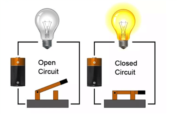
We can say, an electronic circuit is a closed-loop or circular path where the electric current can flow. A closed-circuit form the circular path which starts and end with the same point. Unlike, the open circuit has a discontinuity in the path.

Now, we are going to understand some important electronic components.
Check out Introduction to Breadboard here.
1. Breadboard:

We are going to use Breadboard in our circuit and it is an essential tool for designing temporary circuits and prototyping. The holes in a breadboard are connected vertically and horizontally in columns and rows respectively.
2. Switch :

Electrical switches are mainly used for the interruption in the current path. By interrupting the circuit it can be switched off and switched on.
3. Resistor :

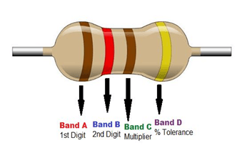
Resistors are a passive component in electronics that are used to limit the flow of current in a circuit. Most of the resistors have colored strips on the outer side, so we can calculate the resistor values using color code. The ohm (symbol: Ω) is the SI unit of resistance which is offered by the resistor.
4. Light-Emitting Diode (LED) :

LED is a two-terminal semiconductor electronic component which emits light when an electric current flow through it. It produces light of different colors, it depends on the substance used inside the LED.
Now, its time to create a basic circuit, we will be combining everything we’ve learned till now. This will be a great starter project for the beginners and I am sure, this will build your confidence.
Know What Is An Inductor and How its work here.
Here, we are using a breadboard to design a circuit, it will a temporary circuit, and no need to solder it together.

Steps:
- Connect the 9V battery to the breadboard.
- Connect the positive terminal (red wire) of the battery to the positive terminal and the negative terminal (black wire) should be connected to the negative terminal of the breadboard.
- Insert the LED on the breadboard, longer terminal is the Anode and the shorter one is the cathode.
- Place the resistor between the anode of the LED and the positive side of the battery as shown in the image above.
- Place the connection between the cathode terminal of the LED and switch.
- Place the connection between the switch and the negative terminal of the battery.
- Once the switch is ON LED start glowing.
Congratulations! Here, we have completed our first circuit.
Thank you for your time.
You may interested in:
How Transistors Work – A basic Explanation
Introduction to MOSFET: Metal Oxide Semi-Conductor Field Effect Transistor