An amplifier is an electronic device that increases the power, voltage, or current of a signal—making it stronger without changing its content. Whether you’re exploring how audio systems boost sound or how signals are transmitted in communication systems, amplifiers play a critical role.
In this guide, you’ll learn exactly what an amplifier is, the main types of amplifiers, and how each one functions. If you’ve searched for “types of amplifiers” or “amplifier definition,” you’re in the right place for clear and concise answers.
Table of Contents
What is an Amplifier?
In simple words, an amplifier is a device that boosts a signal’s strength. It takes a weak electrical signal (like a soft sound or a faint radio wave) and makes it stronger, louder, or more powerful—without changing its original content.
A Glimpse Into History
The journey of amplifiers began with vacuum tubes in the early 1900s, revolutionizing how we process sound and signals. Fast forward to today, we use transistors and integrated circuits, making amplifiers smaller, faster, and more reliable.
Curious about how transistors play a role? Check out our guide to how transistors work.
How Does an Amplifier Work?
An amplifier’s job is simple: take a tiny input signal, amplify it using energy from a power source, and deliver a stronger output signal.
Imagine you’re whispering into a megaphone. The megaphone (acting like an amplifier) doesn’t change your words; it just makes them louder so that the person across the room can hear you.
Key Concepts
- Input Signal: The weak signal, such as your soft voice.
- Gain: The amount of amplification applied (how much louder your voice becomes).
- Output Signal: The amplified version of your voice—clear and strong!
Want to know more about how electronics amplify signals? Head over to this basics of electronic circuits article.
Types of Amplifiers
Amplifiers aren’t one-size-fits-all—they come in different types depending on what they’re used for. Let’s look at the major categories:
1. Based on Functionality
- Voltage Amplifiers: Boost voltage levels, ideal for signal processing.
- Current Amplifiers: Focus on increasing current.
- Power Amplifiers: Provide high power output, perfect for driving speakers.
2. Based on Configuration
- Class A Amplifiers: High-quality sound with minimal distortion but lower efficiency.
- Class B Amplifiers: More energy-efficient but may introduce some distortion.
- Class AB Amplifiers: A blend of Class A’s quality and Class B’s efficiency.
- Class C Amplifiers: Extremely efficient, designed for radio frequency (RF) applications.
3. Based on Applications
- Audio Amplifiers: Found in your speakers and headphones.
- Operational Amplifiers (Op-Amps): Used in precision instruments.
- RF Amplifiers: Handle high-frequency signals for communication systems.
Differences between voltage amplifier, current amplifier, and power amplifier:
| Parameter | Voltage Amplifier | Current Amplifier | Power Amplifier |
|---|---|---|---|
| Amplifies | Voltage | Current | Power (Voltage x Current) |
| Input Impedance | High | Low | Variable |
| Output Impedance | Low | High | Low |
| Purpose | Increase voltage | Increase current | Increase power |
| Load | High impedance | Low impedance | Variable |
| Efficiency | Typically lower | Typically higher | Moderate to high |
| Applications | Audio amplifiers, RF amplifiers | Current sources, transimpedance amplifiers | Audio power amplifiers, RF power amplifiers |
Classification of Power Amplifiers
Power amplifiers are classified as different classes, which states the variation of the output signal with respect to the applied input signal.
a. Class A
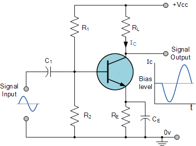
In this class A power amplifiers, the output current flows for overall i.e., 360﮲ of the input cycle. It only operates on the linear region of the load as the operating point is so selected which gives us exact output as that of input.
Here, the maximum possible efficiency is of 50%. This class is used when we simply want a distortion-free output.
Let’s look at the circuit diagram of class A amplifier:

b. Class B
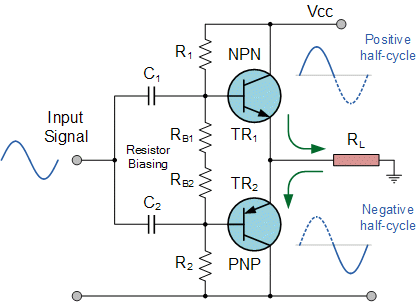
In this class B Amplifier, the transistor is biased in such a way that the current flows only during the positive half input cycle. In this two complementary transistors are used which receive the input signal of equal magnitude but opposite in phase.
When the input is applied at the center-tapped secondary of transformer it generates two identical signals of opposite phase and the two transistors are driven by these two input signals.

c. Class AB
It is a combination of class A and class B type of power amplifiers. This class was basically introduced to eliminate crossover distortion that occurs in class B.
In this type, the angle of conduction lies somewhere between 180﮲ to 360﮲. Here, the transistor biasing is done in such a way that operating point Q lies near cut-off voltage.

d. Class C
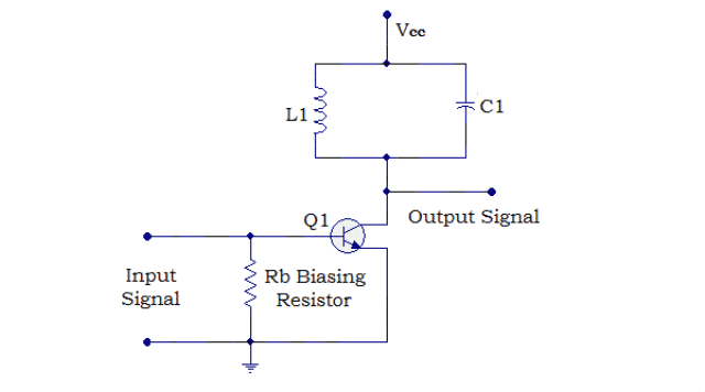
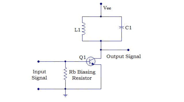
Class C power amplifier is designed to provide the highest efficiency of about 80%. These are biased in such a way that it operates for less than 180﮲ of the input signal but provides the full output signal in case of resonant frequency tuned circuits.

Comparison of Amplifier Types
Here’s a quick overview of how different types of amplifiers stack up:
| Type | Efficiency | Quality | Uses |
|---|---|---|---|
| Class A | Low | Excellent | High-fidelity audio |
| Class B | Moderate | Decent | Everyday amplification |
| Class AB | High | Balanced | Home and professional audio |
| Class C | Very High | Limited to RF | Communication systems |
Conclusion
Amplifiers are essential components in countless electronic systems, from audio equipment to advanced communication technologies. By understanding what an amplifier is and the different types available—such as voltage, current, power, and operational amplifiers—you gain insight into how signals are controlled and enhanced in real-world applications. Whether you’re a student, hobbyist, or professional, knowing the types of amplifiers and their functions helps you choose the right solution for your needs.
FAQs
What are the main components of an amplifier?
Key parts include transistors, capacitors, resistors, and sometimes inductors.
How is an amplifier different from a speaker?
An amplifier boosts electrical signals, while a speaker converts those signals into sound.
Which amplifier class is best for audio?
Class AB amplifiers are the most popular choice for balancing quality and efficiency.