Table of Contents
Introduction
A MOSFET (Metal-Oxide Semiconductor Field-Effect Transistor) is an electronic switch or amplifier that controls the flow of current using an electric field. It has three main terminals — gate, drain, and source — and it works by applying voltage to the gate to control the current between the drain and source. MOSFETs are widely used in everything from computers to power supplies because they offer fast switching speeds, high efficiency, and low power consumption.
Whether you’re learning about “MOS field effect transistors” or want to understand the “MOSFET working principle,” this guide covers the essentials in a clear, beginner-friendly way.
If you’re new to electronics, you might want to start with this beginner’s guide to basic electronic components for better context before diving into how MOSFETs work.
What is a MOSFET?
MOSFET is a type of field-effect transistor that controls the flow of current using an electric field. It’s preferred in circuits due to its efficiency, fast switching, and low power consumption.
MOSFETs stand apart from BJTs (Bipolar Junction Transistors) and JFETs (Junction Field-Effect Transistors) thanks to their ability to handle higher power levels and operate at higher frequencies. Their development revolutionized the electronics industry by enabling miniaturization and enhanced performance.
How Does a MOSFET Work?
A MOSFET operates as a voltage-controlled switch. By applying a voltage to the gate terminal, you create an electric field that regulates current flow between the drain and source terminals.
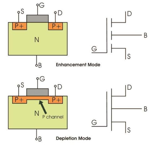
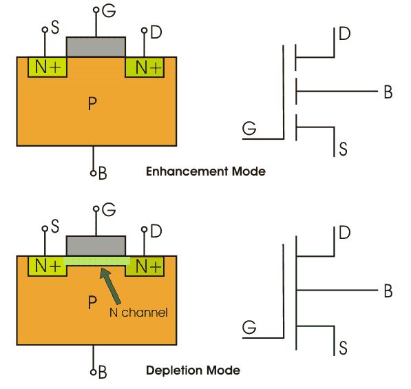
There are two main operation modes:
- Enhancement Mode: Current flows only when voltage is applied.
- Depletion Mode: Current flows even without an external voltage, and applying voltage reduces the flow.
Table :
| Parameter | Description |
|---|---|
| Gate Voltage (Vgs) | Voltage applied between gate & source |
| Threshold Voltage (Vth) | Minimum voltage for MOSFET activation |
| Drain Current (Id) | Current flowing from drain to source |
Types of MOSFETs
MOSFETs come in various types, each suited for specific purposes:
- N-Channel MOSFETs: Allow current flow when the gate voltage is positive.
- P-Channel MOSFETs: Conduct when the gate voltage is negative.
1. P-Channel MOSFET

A P-Channel MOSFET operates when a negative voltage is applied to the gate terminal relative to the source terminal. While less efficient than N-Channel MOSFETs, they are valuable for specific configurations.
How It Works:
- The negative gate voltage creates an electric field that repels electrons and attracts holes (positive charge carriers) into the channel.
- This forms a conductive path between the source and drain, allowing current to flow from the source to the drain.
- The greater the negative gate-to-source voltage (Vgs), the lower the resistance in the channel.
Key Characteristics:
- On-State Resistance (Rds(on)): Generally higher than N-Channel MOSFETs, leading to higher power losses.
- Direction of Current Flow: Current flows from source to drain, as holes (positive charge carriers) dominate the conduction.
- Threshold Voltage (Vth): The minimum negative voltage needed at the gate to activate the MOSFET.
Applications:
- Commonly used in high-side switching configurations, where the load is between the drain and ground.
- Used in circuits where the control signal is referenced to ground, as they can simplify design in such cases.
- Found in battery management systems and low-power switching applications.
2. N-Channel MOSFET

An N-Channel MOSFET is the most commonly used type of MOSFET due to its higher efficiency and better conductivity compared to its P-Channel counterpart. It operates when a positive voltage is applied to the gate terminal relative to the source terminal.
How It Works:
- The positive gate voltage creates an electric field that attracts free electrons into a channel between the source and drain terminals.
- This channel forms a conductive path, allowing current to flow from the drain to the source.
- The higher the gate-to-source voltage (Vgs), the lower the resistance in the channel, improving current flow.
Key Characteristics:
- On-State Resistance (Rds(on)): Typically lower than P-Channel MOSFETs, resulting in lower power losses.
- Direction of Current Flow: Current flows from drain to source, as electrons (negative charge carriers) are the primary mode of conduction.
- Threshold Voltage (Vth): The minimum positive voltage required at the gate to turn the MOSFET on.
Applications:
- Used in switching circuits for power supplies and inverters.
- Preferred for high-current applications like motor controllers and DC-DC converters.
- Ideal for low-side switching in circuits, where the load is connected between the drain and a positive supply.
Comparison of N-Channel and P-Channel MOSFETs
| Feature | N-Channel MOSFET | P-Channel MOSFET |
|---|---|---|
| Conduction | Drain to Source (Electrons) | Source to Drain (Holes) |
| Gate Voltage | Positive to turn on | Negative to turn on |
| On-State Resistance | Lower (Better efficiency) | Higher |
| Typical Use Case | Low-side switching | High-side switching |
Practical Applications of MOSFETs
MOSFETs are everywhere, from household devices to industrial machinery. Here’s where you’ll find them:
- Switches: MOSFETs control high-speed switching in circuits.
- Amplifiers: Used in audio systems and communication devices.
- Power Supplies: Regulate voltage in computers and gadgets.
- Motor Drivers: Manage motor speed and direction in robotics.
How to Select the Right MOSFET
Choosing the correct MOSFET depends on your application. Key factors include:
- Threshold Voltage (Vth): Ensure it suits your circuit’s operating range.
- On-Resistance (Rds(on)): Lower resistance means higher efficiency.
- Power Rating: Matches the power requirements of your circuit.
To understand how MOSFETs differ from traditional bipolar junction transistors (BJTs), check out our full guide on how transistors work.
Conclusion: Why Understanding MOSFETs Matters
Understanding what a MOSFET (Metal-Oxide Semiconductor Field-Effect Transistor) is — and how it works — is essential for anyone learning electronics or working with modern circuits. Whether used for switching, amplification, or power control, MOSFETs are critical components found in everything from computers to power supplies.
By mastering the MOSFET working principle, you’re building a foundation that will make future topics like power electronics, microcontrollers, and signal processing much easier to grasp.
FAQs
What does MOSFET stand for?
Metal-Oxide-Semiconductor Field-Effect Transistor.
How does a MOSFET differ from a JFET?
MOSFETs use an oxide layer, while JFETs use a junction for control.
Can a MOSFET replace a BJT?
Yes, in many applications, MOSFETs are more efficient.