Introduction
The Arduino is a versatile microcontroller that opens the door to countless DIY projects. Among the simplest yet most educational projects is interfacing an Arduino with a 7-segment display. This guide will show you how to connect, code, and troubleshoot your display, making it perfect for beginners.
Whether you’re building a digital clock, a counter, or a thermometer, learning this skill is foundational. Let’s dive in and bring your projects to life!
Take your Arduino skills further with this tutorial on temperature measurement using Arduino.
What is a 7-Segment Display?
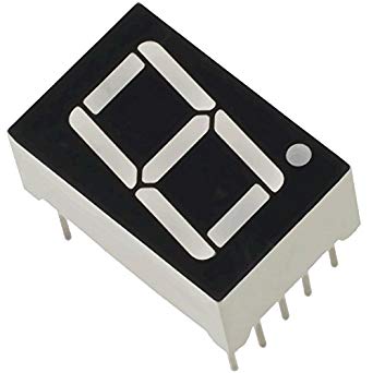
A 7-segment display is a simple electronic component used to display digits. It consists of seven LEDs (segments) arranged in a way that can form numbers 0 through 9.

Types of 7-Segment Displays:
- Common Anode: All anodes are connected to a common pin, and segments are controlled by connecting cathodes to ground.
- Common Cathode: All cathodes are connected to a common pin, and segments are controlled by supplying voltage to the anodes.
| Feature | Common Anode | Common Cathode |
|---|---|---|
| Power Source | Connected to VCC | Connected to GND |
| Control | Negative voltage to segments | Positive voltage to segments |
Components Needed:
- Arduino UNO board
- 7-segment display (common cathode or anode)
- Breadboard
- Jumper wires
- Resistors (220Ω for each segment)
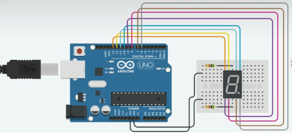
Connection Diagram:

Pin Connections:
| Arduino Pin | 7-Segment Segment | Resistor Included |
|---|---|---|
| Pin 2 | Segment A | Yes |
| Pin 3 | Segment B | Yes |
| Pin 4 | Segment C | Yes |
| Pin 5 | Segment D | Yes |
| Pin 6 | Segment E | Yes |
| Pin 7 | Segment F | Yes |
| Pin 8 | Segment G | Yes |
| Pin GND | Common Cathode | No |
For more ambitious projects, dive into building a robot with Arduino using this comprehensive guide.
Arduino Code
Below is the Arduino code to display numbers 0–9 sequentially on the 7-segment display:
// Define pins for each segment
int segmentPins[] = {2, 3, 4, 5, 6, 7, 8}; // A, B, C, D, E, F, G
// Segment patterns for digits 0-9
int digits[10][7] = {
{1, 1, 1, 1, 1, 1, 0}, // 0
{0, 1, 1, 0, 0, 0, 0}, // 1
{1, 1, 0, 1, 1, 0, 1}, // 2
{1, 1, 1, 1, 0, 0, 1}, // 3
{0, 1, 1, 0, 0, 1, 1}, // 4
{1, 0, 1, 1, 0, 1, 1}, // 5
{1, 0, 1, 1, 1, 1, 1}, // 6
{1, 1, 1, 0, 0, 0, 0}, // 7
{1, 1, 1, 1, 1, 1, 1}, // 8
{1, 1, 1, 1, 0, 1, 1} // 9
};
void setup() {
// Set all segment pins as output
for (int i = 0; i < 7; i++) {
pinMode(segmentPins[i], OUTPUT);
}
}
void loop() {
// Cycle through digits 0-9
for (int num = 0; num < 10; num++) {
for (int i = 0; i < 7; i++) {
digitalWrite(segmentPins[i], digits[num][i]);
}
delay(1000); // Display each digit for 1 second
}
}
Conclusion
By following this guide, you now have the knowledge to interface an Arduino with a 7-segment display successfully. From wiring to coding, you’ve learned essential techniques that can be applied to various projects, such as counters, clocks, and more. As you practice, explore advanced concepts like multiplexing and animations to further enhance your skills.
Don’t forget to share your experience or ask questions in the comments below. Keep experimenting and bringing your creative ideas to life!
Understand the differences between Arduino and Raspberry Pi to choose the right platform for your next project.