In today’s world of electronics and embedded systems, integrating an Arduino with a 7-segment display is a fundamental yet crucial project. Whether you’re building a simple counter, timer, or even more complex system, mastering this task will enhance your understanding of basic electronics, data handling, and microcontroller interfacing. In this blog post, we’ll walk you through the process of interfacing an Arduino with a 7-segment display.
Table of Contents
Introduction
Displaying information like numbers is critical for many electronic projects, from basic digital clocks to industrial controllers. One of the simplest and most efficient ways to do this is by using a 7-segment display. When combined with an Arduino, a 7-segment display can easily present numerical data in an understandable way, helping developers and hobbyists to communicate real-time information.
But here’s the catch: how do you interface these two components efficiently? Let’s dive into it.
The Challenge of Displaying Numerical Data
One of the first challenges in many Arduino projects is displaying real-time data. Whether it’s a temperature reading, sensor data, or simply a counter, presenting numerical data in an easy-to-read format is essential.
Key Issues:
- Complexity: Using multiple LEDs to display numbers can be cumbersome. You would need several pins for each LED, and manually controlling each can become complex as the number of digits increases.
- Space: Multiple individual LEDs consume more space, which is inefficient when building compact devices.
- Power Consumption: Powering individual LEDs demands more current, which isn’t ideal in energy-constrained projects.
If you’re trying to show numbers or simple symbols, it becomes clear that controlling individual LEDs is not an efficient solution.
Issues When Using Multiple LEDs for Numeric Displays
Without an efficient display method, you risk facing several issues:
- Pin Limitation: Arduino Uno, for example, has 14 digital I/O pins. Using 7 or more pins just for a simple numeric display is not an optimal use of resources.
- Coding Complexity: Programming individual LEDs to represent different numbers becomes time-consuming, prone to errors, and hard to debug.
- Power Consumption: Driving multiple LEDs at once can quickly drain the power, especially in battery-operated projects. Imagine driving 7 LEDs per digit for a 4-digit number. This would mean controlling 28 LEDs simultaneously.
This approach makes your project less scalable and less efficient. The more LEDs you use, the more wires, resistors, and power your system will demand.
Why the Arduino and 7-Segment Display is a Better Approach
The 7-segment display is a time-tested solution to these problems. It provides a simple way to display numbers using only seven LEDs (or segments) for each digit. When you connect the 7-segment display to an Arduino, you can efficiently display digits using fewer resources.
Why This Combination Works:
- Fewer Pins: With a 7-segment display, you only need 7 pins (or 8, including the decimal point) to control all segments. This drastically reduces the number of connections required compared to using individual LEDs.
- Easy to Control: A 7-segment display is easy to drive using the Arduino, and it’s straightforward to write code that makes the display show different numbers.
- Efficient Use of Power: Since you’re only lighting the necessary segments, this solution uses less power than trying to control multiple individual LEDs.
- Scalability: If you need to display more than one digit, you can multiplex the displays, saving even more pins and power.
Let’s now dive into the practical steps.
Components Needed
To interface an Arduino with a 7-segment display, you’ll need the following components:
- Arduino (Uno, Nano, etc.): Acts as the brain to control the display.
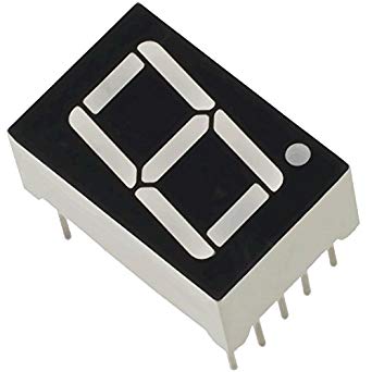
- 7-Segment Display: You can use either a common anode or common cathode type. A common anode means that all the anodes of the LEDs are connected together, while in common cathode, the cathodes are connected.
- Resistors (220Ω): To limit current to each segment.
- Breadboard and Jumper Wires: For easy prototyping and connection.
Optional:
- 74HC595 Shift Register: If you’re short on Arduino pins, you can use a shift register to control multiple segments with fewer pins.
Wiring the 7-Segment Display to Arduino
Pin Layout:
A typical 7-segment display has 10 pins. Here’s how the pins relate to the segments:
- a (top segment)
- b (top right)
- c (bottom right)
- d (bottom segment)
- e (bottom left)
- f (top left)
- g (middle segment)
- dp (decimal point, optional)
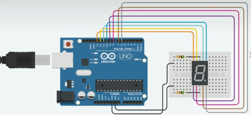
Wiring Diagram:
- Connect pin A of the display to Arduino digital pin 2.
- Connect pin B to Arduino digital pin 3.
- Continue connecting each pin (C to pin 4, D to pin 5, etc.).
- Connect the common anode or cathode pin to 5V or GND based on your display type.
- Place 220Ω resistors between each segment pin and the Arduino to limit current.
Arduino Code for Driving the 7-Segment Display
Here’s a basic code snippet to control a single-digit 7-segment display:
// Define pins for each segment
int a = 2;
int b = 3;
int c = 4;
int d = 5;
int e = 6;
int f = 7;
int g = 8;
void setup() {
// Set all segment pins as output
pinMode(a, OUTPUT);
pinMode(b, OUTPUT);
pinMode(c, OUTPUT);
pinMode(d, OUTPUT);
pinMode(e, OUTPUT);
pinMode(f, OUTPUT);
pinMode(g, OUTPUT);
}
void loop() {
// Display number 1
digitalWrite(a, LOW);
digitalWrite(b, HIGH);
digitalWrite(c, HIGH);
digitalWrite(d, LOW);
digitalWrite(e, LOW);
digitalWrite(f, LOW);
digitalWrite(g, LOW);
}
This code sets up the Arduino to control each segment of the display. You can expand the code by writing more functions for different numbers (0-9) and symbols.
Optimizing the Solution: Multiplexing for Multiple Displays
Multiplexing is an effective technique when you want to control multiple 7-segment displays with fewer pins. Here’s how it works:
- Instead of driving all the segments simultaneously, you can control them one at a time very quickly.
- The human eye won’t notice the switching because it happens so fast (above 60Hz).
For example, if you have four 7-segment displays, you can connect all the segments of the displays in parallel but control the common cathode (or anode) of each display separately. This means you only need 7 segment pins plus 4 control pins for the displays.
You can use the 74HC595 Shift Register to further reduce the number of pins used by the Arduino. This is particularly useful when you’re working on larger projects with limited pins.
Case Study: Real-World Application of 7-Segment Displays
A notable application of the 7-segment display is in electronic gas pumps. These systems need to display real-time data, such as fuel prices and quantities. The robust, simple nature of 7-segment displays makes them perfect for such environments, as they are both reliable and easy to control.
In one study, a small fuel dispenser manufacturer switched from using LCDs to 7-segment displays. The benefits were:
- Durability: 7-segment displays are more resistant to outdoor conditions.
- Cost-Efficiency: The display setup was more affordable compared to sophisticated LCDs.
- Simple Control: Using an Arduino-based control system simplified the software and hardware interface, making it easier for technicians to maintain and troubleshoot.
This case demonstrates how the combination of Arduino and 7-segment displays provides practical, low-cost solutions in real-world environments.
Connection Diagram:
Conclusion
Interfacing an Arduino with a 7-segment display is a foundational skill for any electronics enthusiast. By addressing the problem of displaying numerical data efficiently, we’ve explored how the 7-segment display offers a more practical, scalable, and power-efficient solution compared to using multiple individual LEDs. Through proper wiring, coding, and the use of multiplexing, you can scale your project to multiple digits and displays.
Whether you’re building a simple digital counter or an advanced sensor display, mastering this skill is key to many future projects. So, go ahead and experiment with your Arduino and 7-segment display setup, and you’ll quickly see how versatile and valuable this combination can be.
FAQs for Interface Arduino and 7 Segment Display
What is a 7-segment display?
A 7-segment display is a type of electronic display device that can be used to display numerical digits and some letters. It consists of seven LED segments arranged in the shape of the number 8, with an additional LED segment for a decimal point.
How do I connect a 7-segment display to an Arduino?
Connect the common pin of the display to either ground or 5V, depending on whether it is a common cathode or common anode display. Then connect each of the seven segment pins to separate digital output pins on the Arduino board. Use current-limiting resistors (220 Ohms) to protect the LED segments.
How do I display a number on a 7-segment display using Arduino?
To display a number on a 7-segment display using Arduino, write the code to set the output pins high or low as per the required pattern to display that number. Refer to the datasheet of your 7-segment display to determine which segments need to be lit up to display a particular digit.
How do I display multiple numbers on a 7-segment display using Arduino?
To display multiple numbers on a 7-segment display using Arduino, you need to use multiplexing. This involves rapidly switching between each digit and displaying them one at a time. Write the code to switch between each digit in a loop and display them one at a time.
Can I display letters and symbols on a 7-segment display using Arduino?
Yes, some 7-segment displays can display letters and symbols as well as numbers. Refer to the datasheet of your display to determine which segments need to be lit up to display the desired letter or symbol.
You may interested in:
Temperature measurement using Arduino : Beginners Guide
Arduino or Raspberry Pi: Which is best for beginners?